Optimal inlet and outlet design was critical for process performance
This novel A-stage process was designed using computational fluid dynamics (CFD). Inlet and outlet pipes were designed, optimal sludge blanket fluidization, primary sludge solids wash out prevented.

This case study describes the CFD-based design optimisation of the novel AAA technology, developed by Dr. Bernhard Wett. At full-scale it is difficult and expensive to test different designs and it is hard to find the optimal configuration.
- In a matter of 2 weeks, we virtually tested subtle pipe modifications and smartly configured the outlet using CFD simulation. One week later, the optimal system was in place.
- System performance after full-scale commissioning was optimal
- Practical testing of these design changes would have not been possible
- Tens of thousands of EUR and months of troubleshooting were saved

The AAA settler is a novel A-stage wastewater treatment technology developed by our client Dr. Bernhard Wett (Austria). We helped design the systems in Alta Badia (Italy) and Strass (Austria). The process consists of two alternating reactors that switch between feeding, aeration and settling regimes. Stable operation means:
- No wash out of A-stage sludge
- Homogeneous fluidization


Computer-based design using a 3D CFD model
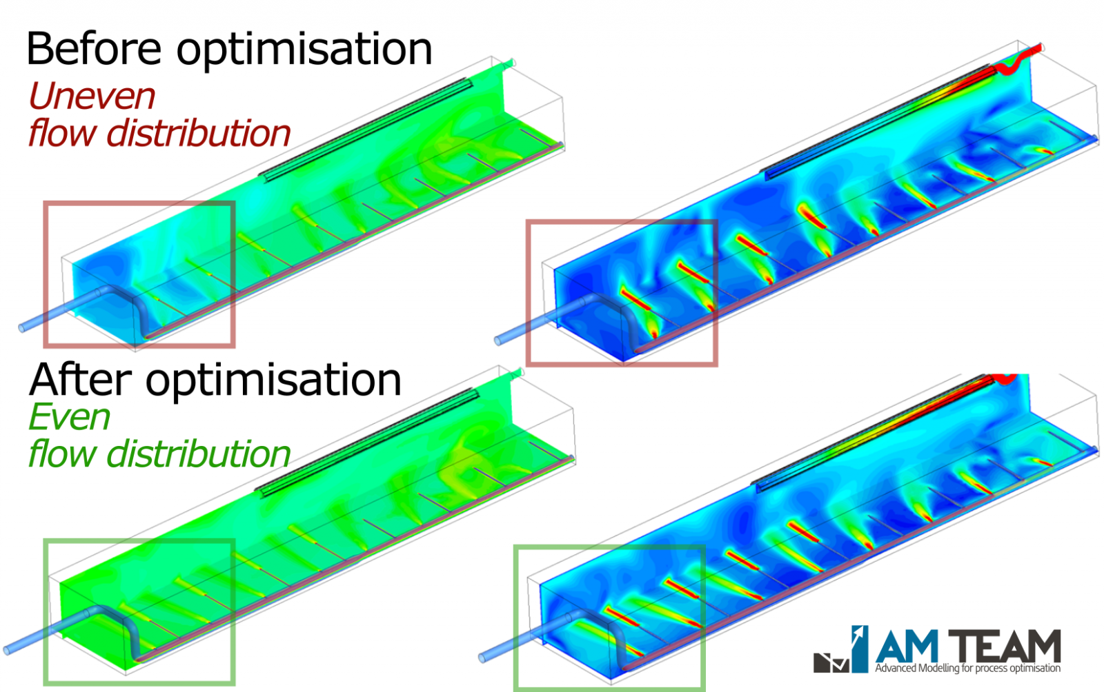
For the AAA case at the Alta Badia WWTP (Italy), we tested different designs of the inlet and outlet structures in 3D. An optimal configuration was found and implemented in practice one week later. As shown in Figure 1, the initial design had uneven flow distribution (dark blue area).
- The colour gradient represents a 'virtual tracer' we inject at the inlet: not in reality, but in the CFD simulation.
- The Rehman-Nopens curves on the right of the figure quantitatively compare the distribution of the virtual tracer across two different designs. In this system, we want a steep curve (indicating good distribution).
- Scenarios B (the modified design) was superior to the 'base case design'. Scenario B was implemented in practice with excellent results. Sludge washout was avoided, and the sludge blanket fluidised optimally.

Figure 1: The distribution of the virtual tracer in the initial design (top) and optimised design (bottom). The more homogeneous green colour indicates optimal distribution. The steep Rehman-Nopens curve for scenario B indicates the quality of that design.
We also conducted CFD simulations for the full-scale plant in Strass, Austria. This time, the reactor was circular instead of the rectangular one in Italy. Also there, the shift in performance is visible after system optimisation.
- As shown in Figure 2, dead zones existed in the base case and could be avoided by altering the design. This led to very steep Rehman-Nopens curves ('base case' = initial design; scenario 1 and scenario 2 were optimised designs).
- Scenario 2 was implemented in reality. The full-scale system as it now operates successfully in Strass is shown in Figure 3.

Figure 2: Rehman-Nopens curves showing the virtual tracer distribution in 3 different candidate designs. Subtle changes in inlet and outlets led to optimal performance. Dead zones (visible in the base case design at the right) could be completely avoided. Scenario 2 was built.

Figure 3: the full-scale AAA system in Srass, Austria, successfully commissioned with nearly perfect flow conditions as a direct result of CFD (source: this online article (in German))
EXTENSIVE BLOG ARTICLE AVAILABLE
Contact us
Suggested Projects


Subscribe to our newsletter


