The latest applications of CFD in drinking water production
Too few water technologists are aware of today's practical application of computational fluid dynamics (CFD). This awareness is important because CFD can solve process engineering problems very fast, effectively and efficiently. The power of CFD lies in:
- The fact that CFD can screen for process and design improvements fast without costly and time taking onsite testing (e.g. 'what would be the impact of changing the air flow rate, inlet structure, ...'),...
- The fact that many of those 'what-if' tests are impossible, too risky or costly to conduct in practice, and that a large fraction of the key CFD insights cannot be acquired in reality.
We talk about time savings in the order of months to years, and cost savings in the order of tens of thousands to hundreds of thousands of EUR. The payback time of CFD projects typically is in the order of months to 1 year. And by using CFD, process technologists get in depth process understanding boosting confidence and knowledge.
This article will look at applications of CFD across whole treatment trains. We will touch upon numerous individual treatment processes used in drinking water production from both surface water and ground water.
The drinking water process trains
There are two main 'species' of drinking water treatment process trains: the 'surface water treatment train' and the 'groundwater treatment train'. While there is some overlap in technologies applied (e.g. softening, sand filtration, final disinfection and storage, ...),the main differences are:
- Groundwater may contain considerable amounts of gases, such as carbon dioxide (CO2) and methane (CH4)
- Surface water contains considerable amounts of dissolved organic carbon (DOC)
Groundwater treatment is hence including aeration and stripping processes while surface water treatment typically includes coagulation-type of organics removal systems (e.g. coagulation/flocculation or dissolved air flotation) and in many cases ozonation.
The main similarities are:
- If centralised softening is applied, both trains contain some kind of softening process (e.g. lime dosing in a basin or pellet softening in a reactor)
- The finished water needs to be stored and distributed, so both trains have 'clean water reservoirs' or 'finished water basins'
Figure 1 shows a surface treatment plant in Amsterdam (operated by Waternet),while Figure 2 shows a groundwater treatment process in Oldeholtpade, Northern Netherlands (operated by Vitens).
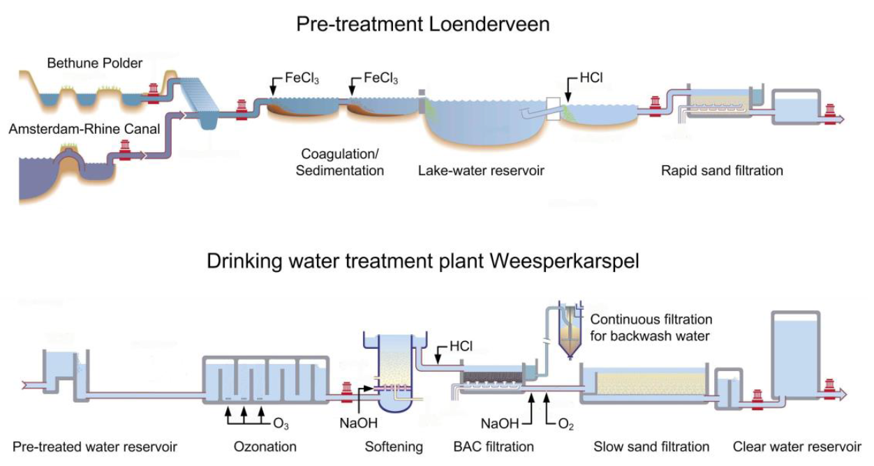
Figure 1: A surface water treatment plant in Amsterdam, characterised by organics removal and oxidation processes (van der Helm et al., 2015 - link to source)
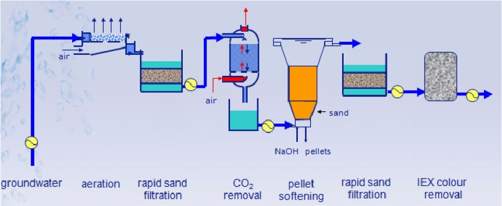
Figure 2: A groundwater treatment plant in Northern Netherlands, characterised by gas removal (i.e. stripping) processes (Chokshi, 2012 - link to source)
A walk through the process trains - the questions CFD can answer
Step 1 - the water intakes
Surface water plants have 'intakes'. They can be 'mixing basins', designed for so-called 'peak-shaving' (i.e. buffering the variability of the source to safeguard the downstream operations from large fluctuations in water quality) and/or 'storage basins', typically larger in volume and meant to store the water for weeks to months. Ideally, the HRD (residence time) is quite uniform and the volume of the expensive basins is used optimally (i.e. no dead zones). Figure 3 shows large-scale CFD simulations of both - the colors indicate a 'virtual tracer' we inject at the inlet. In both cases, the whole CFD project was finished in a matter of 2-3 weeks. Aeration, wind effects, basin geometry, ... were all taken into account.
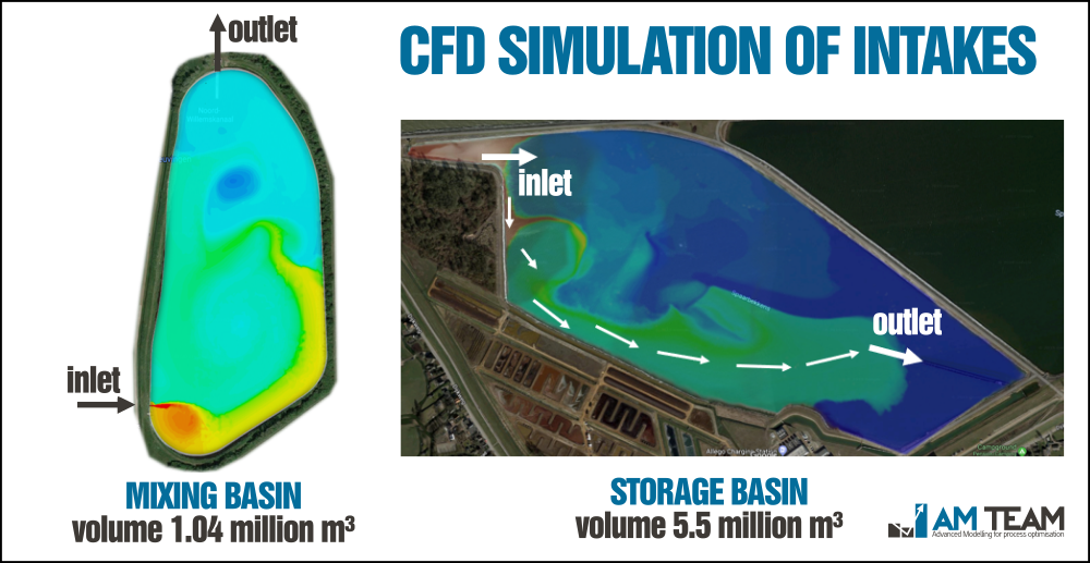
Figure 3: CFD simulations intakes of surface water treatment plants - the 'virtual tracer' indicates shortcircuiting of incoming water
The questions CFD answers by running 'what-if' scenarios:
- How is the peak shaving performance of the basins? How long does it take for a peak to reach the outlet?
- What is the impact of aeration, and what is the optimal position, air flow rates and bubble sizes of the aerators in order to minimise energy consumption and maximise mixing performance?
- How is performance under different conditions? (e.g. flow rate changes, wind and storm, ...)
- How to optimally design/retrofit the basins (e.g. inlet/outlet positioning, geometry, ...)
Here is a video of one of our projects for our customer PWN (NL):
Acknowledgements: PWN (NL),WLN/Waterbedrijf Groningen (NL),Water-link (BE)
Step 2 - organics removal
Coagulation-flocculation and dissolved air flotation are popular processes for DOC removal. By dosing a coagulant (typically 'ferric' (i.e. FeCl3),one 'messes up the charges' of the organics, which means they will suddenly start sticking together by a multitude of mechanisms. In the end, it comes down to a rapid and complete mixing of the coagulant with the water after which the water must be allowed to flocculate in a zone with lower mixing intensity.
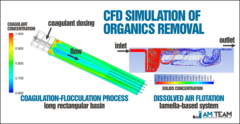
Figure 4: CFD simulation of coagulation (left) and dissolved air flotation (DAF) (right)
The questions CFD answers by running 'what-if' scenarios:
- Where is the optimal coagulant dosing location to achieve the most effective mixing?
- How to design the system to avoid dead zones and short-circuiting?
- What is the local shear gradient ('G') in all of the zones, and how to design for optimal flocculation?
Acknowledgements: Watercare (NZ),De Watergroep (BE),BIOMATH/UGENT (Satpathy et al., 2020 - link to article) (BE)
Step 3 - rapid sand filtration
Rapid sand filtration is the oldest reactor-based water treatment technology. In 900 BC, Ancient Greece was already relying on it to purify water. Back then, a sand filter was a ship filled with sand, perforated at the bottom (source: The quest for pure water - Baker and Wolman - link to book). Today, it is the most widely used water treatment technology in the world due to its reliability and simplicity. Rapid sand filtration knows a cyclic operation consisting of two different phases:
- Filtration phase : the water is fed at the top and percolates through the filter - water is being treated
- Cleaning phase: water, and later a water/air mixture are purged from the bottom through nozzles, allowing the sand bed to expand and intensively mix - the filter is being cleaned
Figure 5 shows the deposition of solids on the bed surface during filtration using two very different sand filters. The video shows the cleaning phase, including the transition to water cleaning to water/air cleaning. To the best of our knowledge, it is the first ever 3-phase CFD simulation of sand filtration at full-scale.
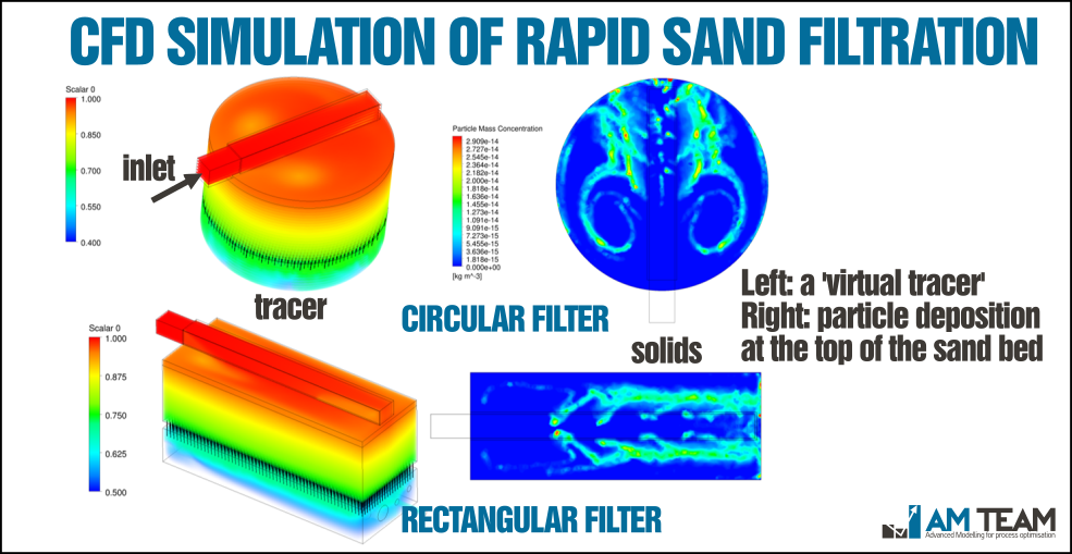
Figure 5: CFD simulation of the filtration cycle: tracer transport (left) and particle deposition (right)
The questions CFD answers by running 'what-if' scenarios:
- What is the optimal inlet configuration and water level height to obtain even solids loading over the filter bed?
- How should the bottom structure design look like to avoid shortcircuiting (filtration) and optimal backwashing (cleaning)?
- What is the impact of shape and dimensions, and how does a standardised design look like?
Acknowledgements: Vitens (NL)
Step 4 - ozonation (or advanced oxidation)
Ozonation was 'born' in France over a century ago. While it is a commonly applied drinking water treatment technology, the number of applications in wastewater treatment and reuse is growing rapidly. Ozonation is both a very strong disinfectant (i.e. deactivation of micro-organisms, bacteria and viruses) and oxidant (i.e. oxidation of inorganic and organic species, including taste and odour components). The design of ozone dissolution systems and reactors can benefit tremendously from CFD, given the CapEx and OpEx related to this process, and the risk of byproduct formation (e.g. bromate) when designed and operated inappropriately. In collaboration with the international partners HRSD (US) and Dynamita (FR),AM-TEAM has developed a novel kinetic ozonation model predicting ozone decay, hydroxyl radicals (HO*),organic target pollutants and bromate in real matrices: AMOZONE. HRSD currenlty uses this model in it's flagship reuse project SWIFT. A full webinar recording on that model is available. Different ozone dissolution methods (e.g. fine bubble diffusion or sidestream injection) can be readily simulated using 2-phase CFD. Figure 6 shows one of the ozone reactors we simulated. Figure 7 shows the result of the direct CFD-kinetic coupling predicting O3, HO*, bromate, ... in 3D.
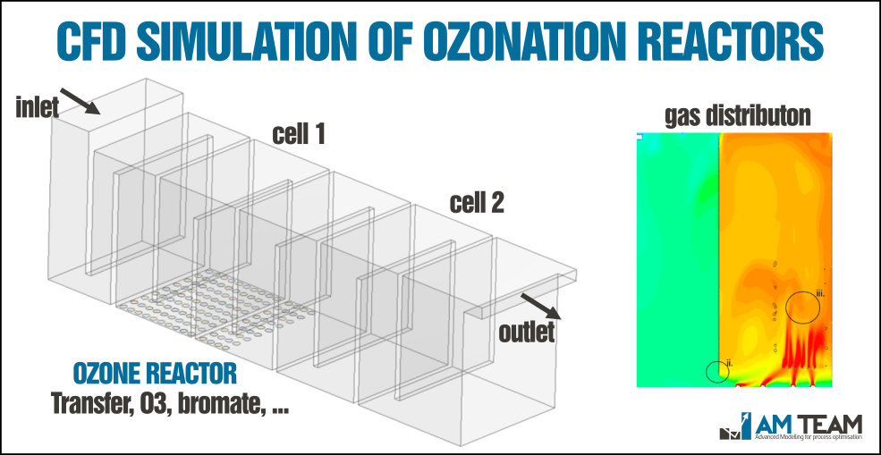
Figure 6: A typical ozone contactor - CFD can lead to drastic improvements in performance and cost
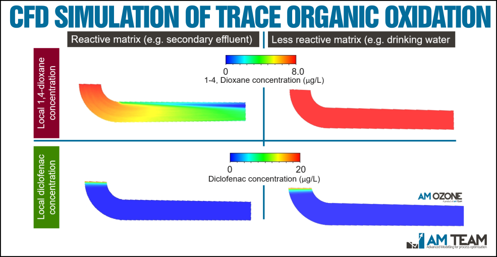
Figure 7: Direct CFD-kinetic simulation: the 3D concentration profiles of two very different trace organics in a pipe reactor - Diclofenac is easily removed by ozone, while 1,4-Dioxane only reacts with HO* radicals
The questions CFD answers by running 'what-if' scenarios:
- How to design for maximum gas/liquid mass transfer?
- Which reacor design gives optimal mixing and uniform HRT? (e.g. baffling etc.)
- Which CT can be expected at different conditions and doses?
- Which bromate levels can be expected, and how to minimise/suppress bromate?
- How is the expected removal of a wide selection of target contaminants?
Acknowledgements: HRSD (US),Dynamita (FR),Dunea (NL),Waterschap De Dommel (NL)
Step 5 - pellet softening
Softening does not always occur after oxidation, neither does it always occur in reactors (i.e. 'softeners'). For example, NaOH is dosed at the intake of the right basin in Figure 3 (i.e. directly upon intake). Softening reactors however need careful designing as they typically are a very sensitive process of which performance decrease does not stay unnoticed (i.e. hardness increase). We have simulated such systems multiple times, saving our customers large amounts of experimental time and investments (i.e. a 'pilot reactor' of this size is not cheap). The leading Dutch utility Vitens uses this output in it's flagship digitalization project SLIMM. A whole size distribution of pellets is included in the simulation, and we account for the 'heaviness' of the pellet bed, impacting the mixing of the water and dosed hydroxyde (i.e. NaOH or Ca(OH)2).
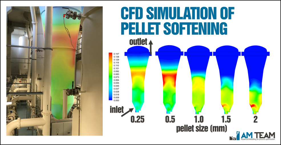
Figure 8: CFD simulation of a 12m pellet softening reactor at Tull en 't Waal (Vitens - NL) - the colors indicate the local concentration of a certain pellet size fraction
The questions CFD answers by running 'what-if' scenarios:
- How to mix the dosed chemicals optimally and fast?
- How to avoid shortcircuiting through the pellet bed?
- Can reactor size be reduced without losing performance?
- How to obtain optimal precipitation kinetics driven by opitmal stratification of the pellet size classes?
Acknowledgements: Vitens (NL)
Step 6 - final disinfection, storage and distribution
Pellet softening typically gets followed by rapid sand filtration. Given it's earlier coverage, we come to the final stage: final disinfection, storage and distribution. Given the craftmanship and investments needed to produce high quality drinking water, careful final handling is important to keep the quality. A wide variety of disinfection methods are used. Examples are chlorine or monochloramine dosing and UV disinfection (the latter leads to no residual). Disinfectants can be dosed either in the basins or prior to entering them. An example of the virtual design of a new finished water reservoir is shown in Figure 9. Over 15 different designs were tested in a matter of a few weeks, leading to optimal mixing and saving CapEx by minimising baffles.
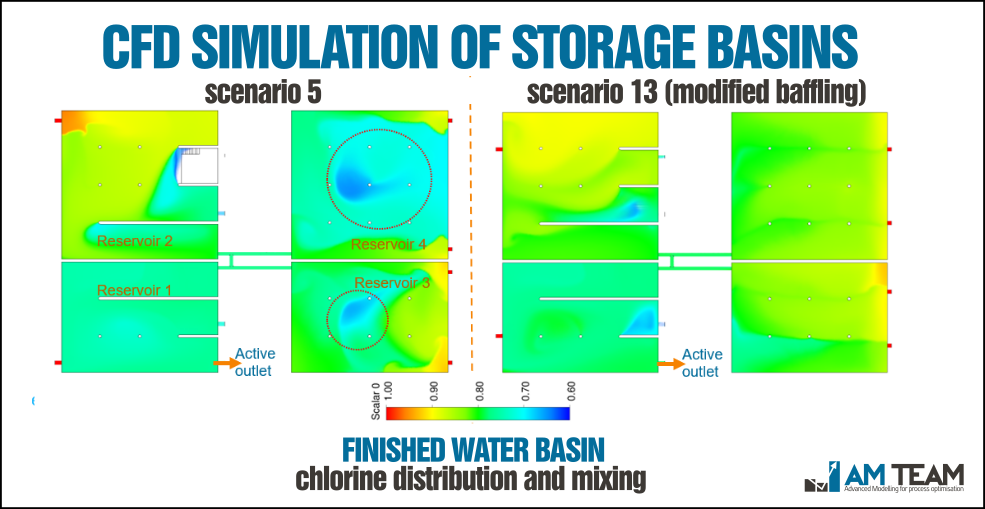
Figure 9: CFD simulation of four interconnected finished water reservoirs (Pidpa, BE)
After storage, the water may be pumped to intermediate storage and pressure reservoirs. Also in those reservoirs, mixing is of crucial importance. The following video shows the filling of one of the 'water towers' of our Belgian customer Pidpa. Together with Pidpa we did in depth investigation of the impact of design and operational decisions on water ageing.
Figure 10: Looking through the wall of a water reservoir: the daily filling
The questions CFD answers by running 'what-if' scenarios:
- How to minimise the CapEx (eg less concrete) and OpEx (eg pumping costs) of those reservoirs?
- What is the fraction of 'older water' left after a daily cycle?
- How to redesign or better operate the reservoirs to minimise water ageing?
- Where and how to dose disinfectants?
Acknowledgements: Pidpa (BE),Vitens (NL)
Stripping processes...
Yes, we have not covered the stripping processes in ground water treatment. However, simulaitons look similar to other gaseous multiphase simulations such as ozonation.
FINAL CONCLUSION
As you probably noticed, there are numerous applications of CFD in drinking water treatment, storage and distribution. Only by brining out cases like this, practitioners can be made aware of the current maturity and practicality of this modern engineering tool. May the takehomes be that:
- The payback times of CFD are very low (typically a few months to <1 year) and
- Complete CFD projects are finished within 2-4 weeks (including intermediate meetings)
Additional resources
- Extensive video material at our YouTube channel 'AM-TV'
- Extensive blogs at our website
- Follow AM-TEAM at LinkedIn
And with this, we want to thank our great customers, partners and team members. CFD figures are nice, but it's the people that make collaborations truly colorful.
Contact us


Subscribe to our newsletter


