A unique overview of the application of CFD in the water industry
Water utilities and technology companies worldwide now rapidly embrace Computational Fluid Dynamics (CFD) as a tool for process optimisation, design and virtual piloting. CFD is a realistic 3D computer simulation of a treatment process, largely based on flow physics. It allows you to 'play' with any design or operational variable on the computer to obtain the process you want faster and at lower risk and cost.
[Nederlandstalige versie beschikbaar]
This article gives you:
- A short description of the stat of the art
- 6 different case examples that show the wide variety of problems it can solve
What is advanced CFD?
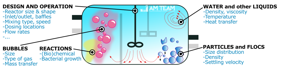
Water/wastewater treatment processes can contain more than only water: gas bubbles, particles and (bio)chemical reactions are important in many cases. Advanced CFD takes into account one or more of these process phenomena. This then leads to very realistic 3D models that can complement, reduce or replace real measurements and experiments.
In the recent live Webinar of the International Water Association (IWA) with over 300 attendees, AM-TEAM showed how operational and design problems can be solved using CFD. Here's a short video.
IWA Webinar Computational Fluid Dynamics - Presentation by Wim Audenaert from IWA on Vimeo.
The three reasons why water technologists use advanced CFD
While the questions in the drinking water and wastewater field can differ (e.g. effluent quality vs water safety),it often comes down to three major groups of benefits. The examples that will follow, relate to multiple of these categories.
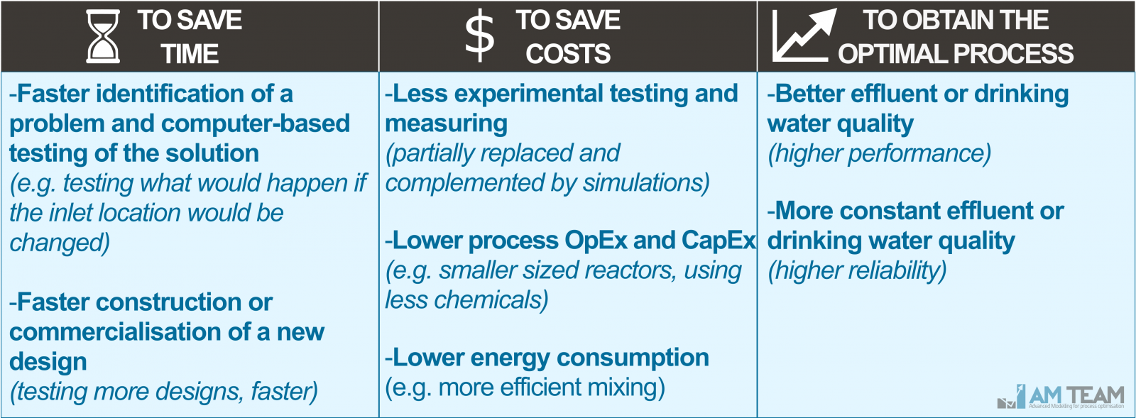
Figure: the three groups of reasons why water practitioners use CFD
We will now discuss different case examples. Click here if you directly want to scroll to the drinking water examples.
Part I: Wastewater examples
Improving effluent quality in a full-scale WWTP by optimising aeration and mixing
OBJECTIVE
This 750.000pe WWTP in the Netherlands was undergoing a retrofit of the aeration. CFD was used to:
- Determine the optimal aerator configuration and
- Optimise the mixing in the three identical bioreactors. Real testing at full-scale would have been costly and risky
APPROACH
9 different bioreactor designs were tested in a couple of weeks whereby mixers and aerators were reconfigured. Bubbles, as well as activated sludge viscosity and biological conversions were realistically accounted for.
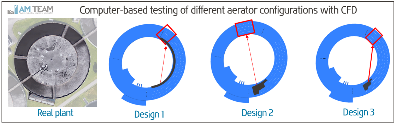
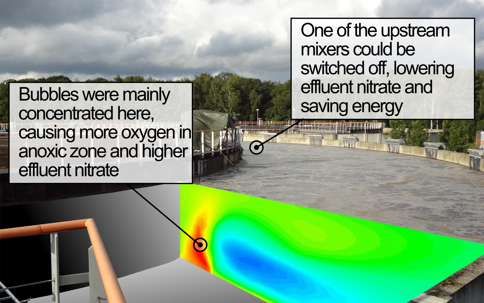
Figure: Example of 'what-if' scenario testing. In this specific case, aerators were moved more upstream, and in some cases, mixers were switched off.
RESULTS
The design scenario with superior performance was implemented, lowering effluent nitrate and saving costs (by switching off a specific mixer at certain flow rates). The model could very accurately predict reality [extensive articles available for further reading]
CFD-based design of a novel A-stage treatment technology
OBJECTIVE
The AAA settler is a novel A-stage wastewater treatment technology that consists of two alternating reactors that switch between feeding, aeration and settling regimes (see AAA website). Testing different inlet and outlet configurations at full-scale was not feasible. Therefore we used accurate CFD modelling to:
- Prevent A-stage sludge wash out and
- Obtain homogeneous fluidization of the sludge blanket
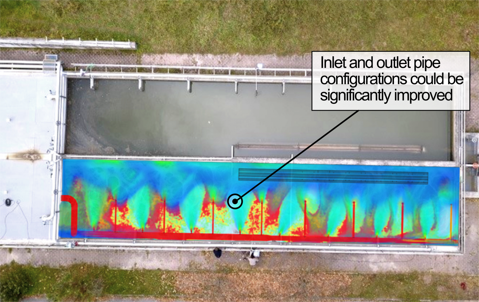
Figure: Air image of the AAA system in Alta Badia (Italy),with overlay of CFD simulations showing solids transport
APPROACH
Accurate CFD simulation was used to test four different inlet and outlet designs virtually. Pipe diameters, lengths and configurations were altered with the 3D CFD model. A-stage sludge was included in the model as a separate solids 'phase'.
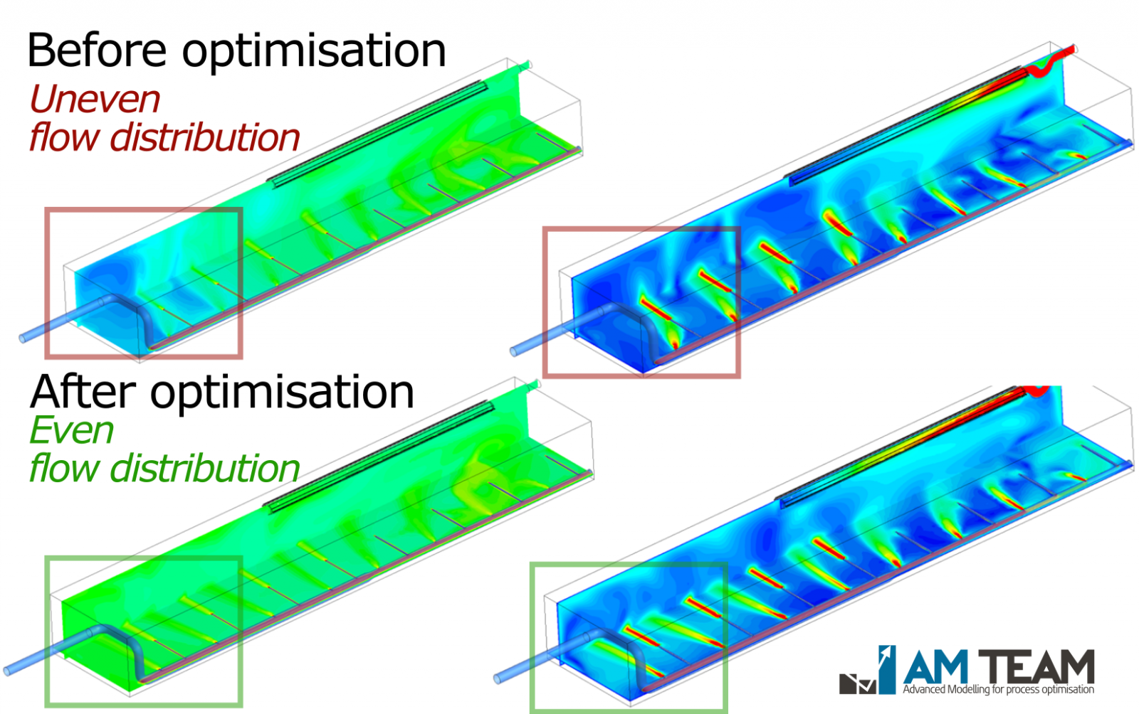
Figure: Influent distribution before and after optimisation (colors indicate a 'virtual' tracer (left) and local velocities (right)
RESULTS
In two weeks time, the optimal design was found and implemented at the plant. The plant now operates optimally with superior performance. Model accuracy was also proven using onsite data. [Further reading: case available]
CFD-based design of Enhanced Biological Phosphorous Removal (EBPR)
OBJECTIVE
Enhanced Biological Phosphorous Removal (EBPR) receives a lot of interest worldwide. Activated sludge is fermented either in the mainstream or sidestream (S2EBPR) to produce the VFAs essential for BioP uptake. We use CFD to:
- Optimally design these systems (inlet/outlet configuration, mixer configuration, reactor design (e.g. baffles),...)
- Optimally operate these systems (intermittent mixing, operation based on flow rate)
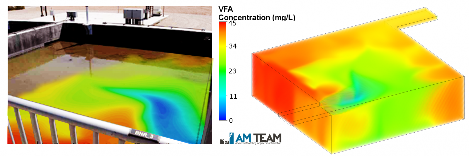
Figure: An unmixed inline fermenter with visible sludge blanket, with 3D CFD simulation of biological conversion (in this case volatile fatty acids - VFAs)
APPROACH
Biological kinetics for phosphorous removal were integrated in CFD, leading to world's first CFD-BioP model. The CFD model calculates the sludge blanket and solids settling as a different 'phase'.
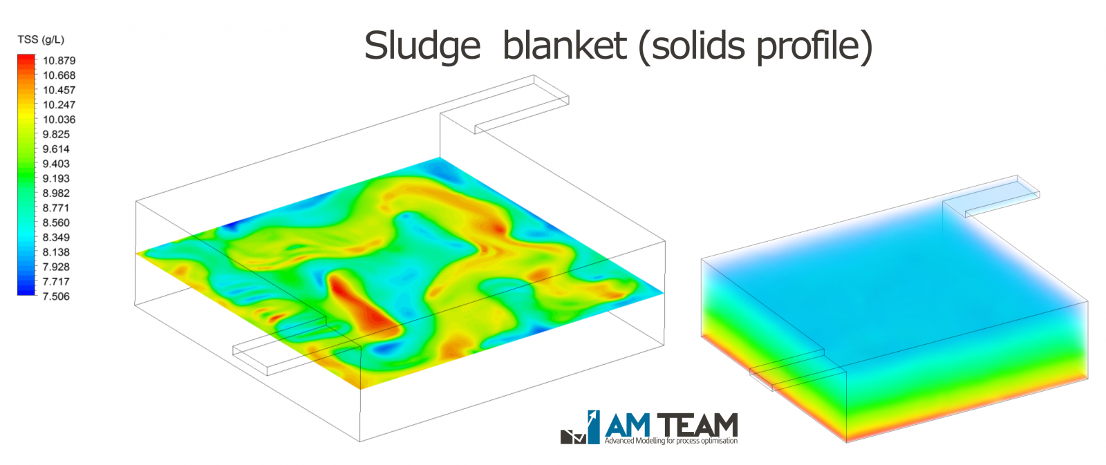
Figure: Sludge blanket calculation (colors indicate the local TSS concentration)
RESULTS
Different full-scale projects are currently ongoing in Europe and North America with different wastewater utilities and partners. In these projects, different designs (baffles/inlet/outlet/...) and mixing strategies (type/speed/time) are being evaluated virtually using the model. The results of the CFD-BioP model are directly comparable to measurement data. [Further reading: case available]
Technologies benefiting from CFD that were not discussed
Conventional and granular activated sludge, shortcut N removal, MBRs, MBBRs, stabilisation ponds, aeration and other mass transfer systems, anaerobic digestion, UASBs, advanced oxidation and ozonation, primary and secondary settling, flotation, electrochemical processes
Are you not interested in drinking water examples? You can jump to the conclusion immediately
Part II: Drinking water examples
Optimising the mixing in large storage and mixing basins
OBJECTIVE
Many drinking water companies treating surface water use large basins to store the water and/or perform peak shaving ('equalize'). At multiple occasions, we have used 3D CFD modelling to:
- Prevent or cure dead zones with high hydraulic residence times
- Prevent or cure shortcircuiting, leading to very low residence time and poor peak shaving
- Save energy in basin operation (e.g. optimise aeration)
- Assess the impact of upstream surface quality dynamics on downstream treatmen
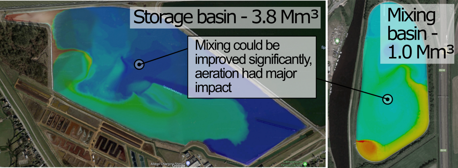
Figure: Two different large scale basins that were modelled with CFD, accounting for aeration and in some cases even wind effects and particle settling
APPROACH
The basins were very realistically modelled, taking into account their real 3D geometry and design, the location and operation of the aeration (if installed) and real flow rates. In some of the cases, wind was taken into account (for very large basins) and particles were simulated (in case the transport of solids was one of the topics to investigate).
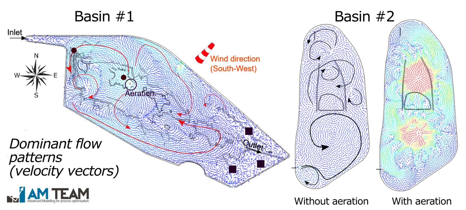
Figure: Important flow patterns observed in two very different water basins (little arrows indicate local flow velocity and direction (dark blue is very low velocity)
RESULTS
In most of the basins simulated, shortciruiting and dead zones were observed. The same CFD models were used ot virtually 'play with' the design (e.g. inlet configuration, aerator location, ...) and operation (e.g. air flow rates) of the basin. In some cases, model validation was performed, with excellent model performance. Further reading: case available
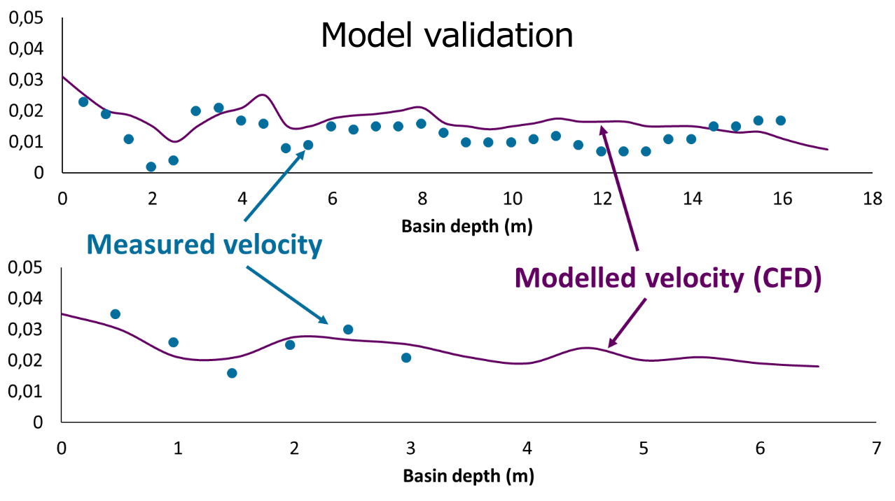
Figure: In some cases, the drinking water company asked for model validation. These two plots illustrate CFD model accuracy (modelled vs simulated velocity as function of basin depth)
[further reading: case available]
Virtual piloting of pellet softening reactors for optimal design
OBJECTIVE
Advanced CFD is very well suited for computer-based reactor design. Often, different real test installations have to be built and run to explore the optimal design. This takes large amounts of time, needs significant man power and leads to high costs (including stainless steel or other expensive material). Testing freedom is hence very limited and uncertainty remains. With this drinking water client, we used advanced CFD to:
- Save significant amounts of time and costs related to physical piloting
- Determine the optimal design for their treatment facilities, in a standardized way
- Reduce the size of reactors to save CapEx
- Produce optimal drinking water quality, reliably (e.g. guaranteed optimal calcium removal)
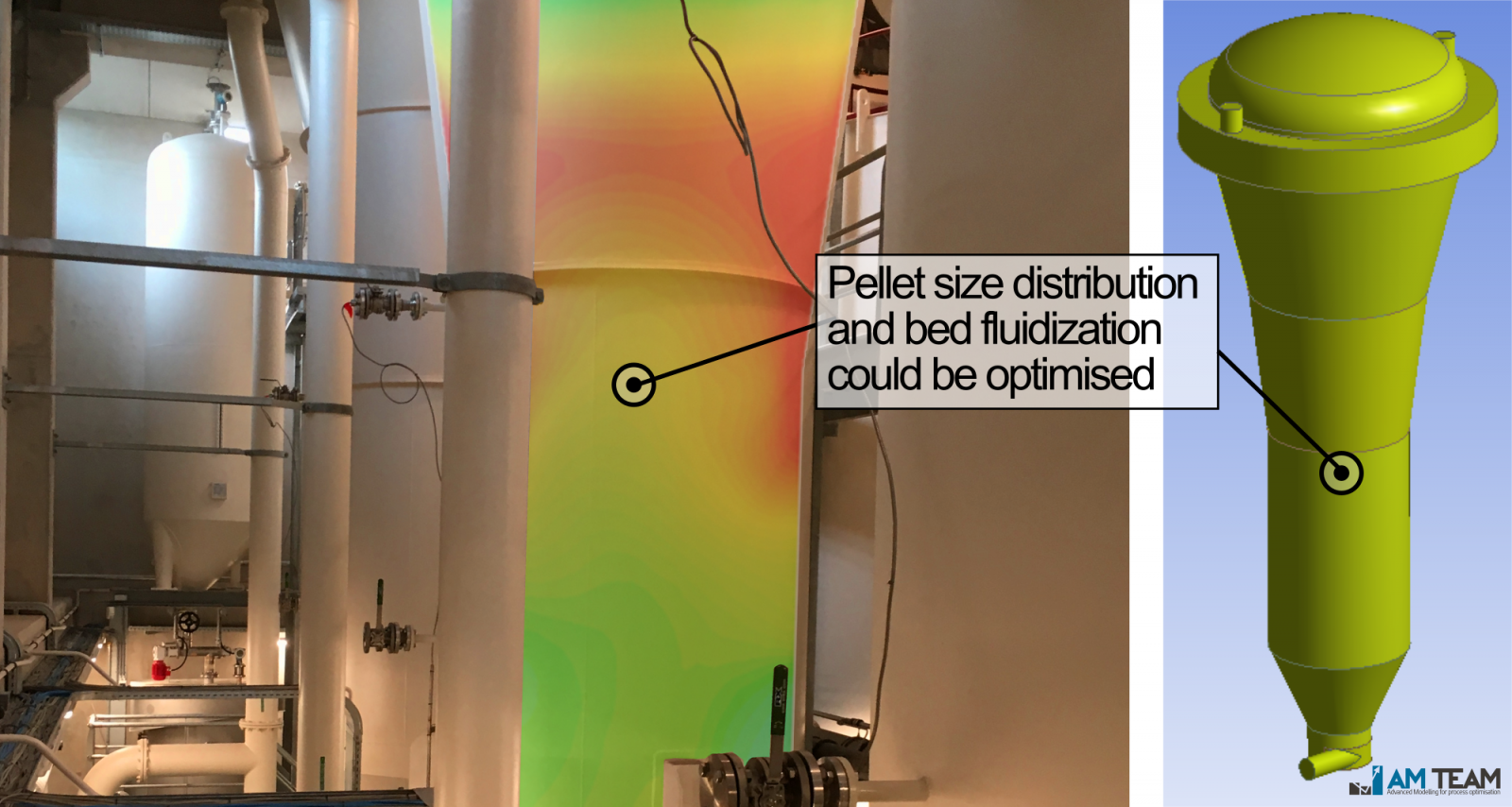
Figure: Full-scale pellet softening reactors, with an overlay of the CFD simulation of one of the pellet size classes - many different designs exist worldwide
APPROACH
Full-scale pellet softeners were modelled by realistically accounting for pellets with different sizes and densities simultaneously in one simulation. This gives a 3D image of the fluidized bed stratification.
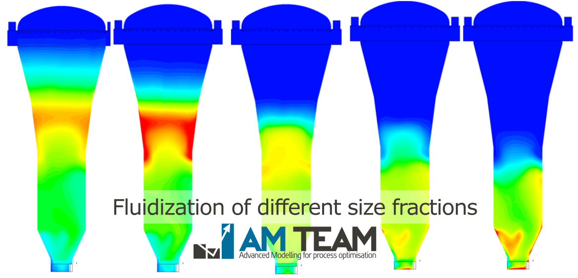
Figure: Fluidization heights of pellets with different sizes and densities (from left to right: small to large pellets)
RESULTS
3D computer-based testing of designs is orders of magnitude faster compared to physical trialling. Model predictions were compared with onsite measurements of pellet sizes and fluidization heights. Together with our client we are investigating novel inlet structures and reactor shapes, virtually. The resolution of 3D data obtained cannot be matched with onsite experiments and measurements. [Further reading: case available]
Reducing microbiological risk in water reservoirs
OBJECTIVE
Water utilities want to minimise the risk of regrowth in their distribution network. Water reservoirs of many different sizes, configurations and shapes are used worldwide. In this drinking water project we investigated the mixing of 'new' an 'older' water in existing water reservoirs and used the same CFD model to:
- Optimise mixing in order to minimise risk (especially during warm weather)
- Investigate energy saving opportunities (pumping energy saving)
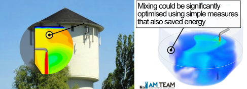
Figure: A 600m³ storage basin ('water tower'' in this case) - color gradients indicate how 'new' and 'older' water mix
APPROACH
We simulated various different storage basins, with very different volumes, shapes (e.g. aspect ratios differed significanlty) and configurations (filling from top vs bottom, from side vs center, ...). 'New' and 'Older' water fractions were quantified in 3D throughout 24h cycles of filling and emptying.
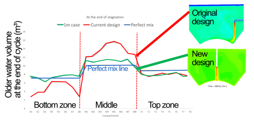
Figure: Old water volume at the end of a 24 cycle in the original reservoir design (red line) and an optimised design using a different filling location (green line)
RESULTS
The design of water reservoirs (shape, aspect ratio, ...) and their inlet/outlet configuration (diameter, horizontal/vertical location) have a huge impact on mixing performance and risk on water aging. We have demonstrated in multiple cases that with often simple measures, risk can be lowered drastically. For example, in some cases (highly design specific!) the outlet pipe was used for filling, leading to superior performance and pumping energy savings. Water reservoirs look simple, but their behaviour is complex and must be understood for optimal performance.
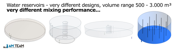
Figure: Some water reservoirs modelled, with very different volumes and designs
[Further reading: case available]
Technologies benefiting from CFD that were not discussed
Aeration and other mass transfer systems, settling processes, flotation, (advanced) oxidation and disinfection, ozonation, ion exchange, membrane processes, contact tanks
Conclusion
Important trends that drive the need for advanced process modelling are process intensification (doing more with less),resource recovery (including water reuse),climate change, more stringent regulation and the speed of change of society and the market. Numerous water and wastewater utilities and technology companies now embrace this concept due to the acceleration, savings and learning it brings. The purpose of this article was to give you a brief but powerful overview of the wide array of applications.
The topic will be presented and extensively discussed at:
- WATERMATEX 2019, Copenhagen (1-4 Sep)
- Weftec 2019, Chicago (21-25 Sep)
Important note from the authors
Subscribing to our newsletter (below) will give you access to much more information like this. Further, we are planning to organise a free webinar in which some examples will be extensively discussed live. You can opt in for the webinar here.
Do you have any questions, or do you think a colleague has to know about this article?
YOU CAN ASK US YOUR QUESTION TODAY
(even in your native language)


Subscribe to our newsletter


